1957-1971 D&W Series Booster installation instructions
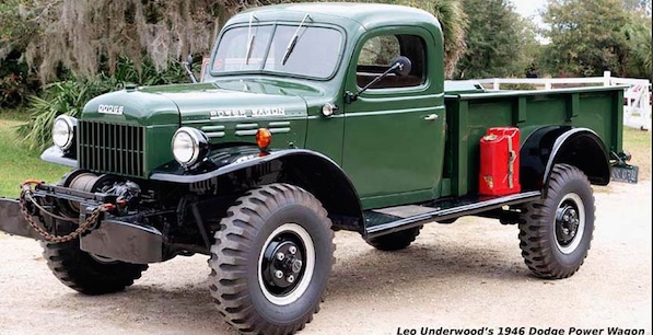
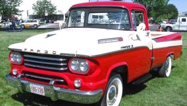
We no longer make our 1976 Chevy boosted master cylinder installation for the 1957 - 1960 Power Giant trucks and all Town Wagons. Below are the instructions so you can do it yourself. The second part of the instructions is for the 1961-1971 sweptline trucks.
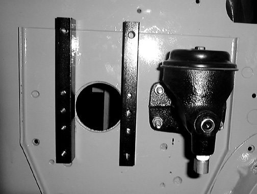
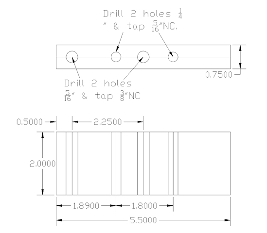
Make two of these mount rails from steel bar stock.

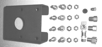
Parts that were Included in the kit:
2 ea. Brake master cylinder adapter fittings.
1 ea. 3/16" brake line plug.
1 ea. Firewall seal.
1 ea. Threaded extension for lengthening the master cylinder push rod ('59-'60 trucks).
1 ea. Tee fitting for installation of brake light switch ('59-'60 trucks).
You will need to purchase the following locally:
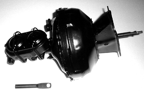
1 ea. 1976 Chevy dual diaphragm booster for C30 pickup.
1 ea. 1976 Chevy master cylinder for C30 pickup.
1959-1960 Installation:
1. Remove your old single circuit brake master cylinder and its push rod.
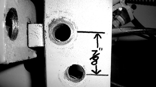
2. Bolt the rails to the firewall as shown below using the 5/16"NC X 1" bolts and split-loc washers provided. If you are doing this by yourself you can reach through the pushrod hole and start the 5/16" bolts. Make sure that the mounts are straight up and down. Don't tighten the bolts yet.
Remove the 1/4" pipe to 1/4" inverted flair fitting from the front opening on your clutch master cylinder and install it in the bottom opening after wrapping its threads with teflon tape. Wrap the 1/4" pipe plug (provided) with a little teflon tape and screw it into the end of the clutch master cylinder as shown. Make sure that the teflon doesn't extend over the end of the fittings or pieces of it may get loose in the hydraulic circuit causing problems. If your clutch MC only has one output opening use the old brake MC for the clutch as they usually have two openings (one for the brake light switch).
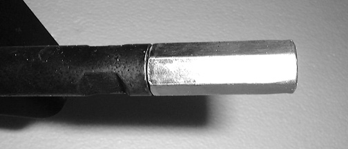
3. Unthread the push rod end from the Chevy booster and enlarge the hole in the end of the push rod from 1/2" to 9/16" so that it will fit your Dodge pedal bolt.

4. Install the counter bored end of the threaded extension onto the booster shaft as shown below and tighten it.
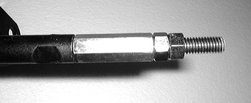
5. Screw the 3/8"NC X 2.150" threaded rod into the other end of the extension as far as it will go then thread the two 3/8" nuts all the way on tightening the one closest to the extension. Leave the other nut finger tight.
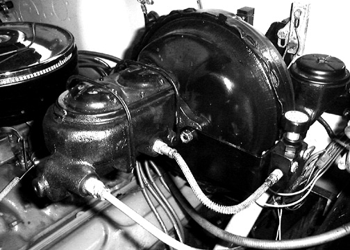
6. Bolt the booster and master cylinder onto the adapter rails using the six 3/8"NC X 1" bolts provided using the two thick 3/8" washers as spacers on the longer top two bolts. Check to make sure that the two master cylinder attach bolts on the booster are perfectly horizontal and the mount rails are vertical. If they are a little off, operation of the unit will not be effected, however it will be a visual irritation whenever you look at it!
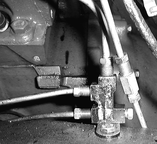
Install the two master cylinder adapters in the outlet ports of the MC. The one that takes 1/4" brake line goes in the forward port and the one made for 3/16" line goes in the rear port. Run a 1/4" brake line from the forward port on the MC down to the top port on the brass brake line junction block on the left frame under the booster.
7. If you are installing a proportioning valve, fasten the adjustable proportioning valve onto its bracket using the two 1/4" x 1-1/2" bolts and nuts with the IN port facing forward and run a 3/16"X 8" length brake line from the rear MC resivour to the P-valve IN port. Your rear brake line will be brought up to the bottom of the Tee fitting which is installed in the other P-valve port marked OUT. Your hydraulic brake light switch is screwed into the rear opening on the Tee fitting.
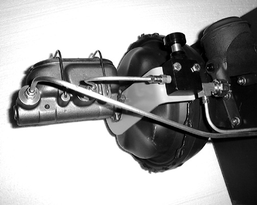
Below is a photo of the brass brake line junction block located on top of the frame under the master cylinder. The 1/4" line from the forward port of the MC can be seen going into the top port. While the rear brake line has been unscrewed from the block and an extension line coupled to it, the extension goes up to the rear port of the MC. The remaining two lines go forward to the front brakes as in the original installation. A 3/16" flair plug is provided for plugging the rear line outlet in the block.
8. Drill a 3/8" hole 7/8" down from the original one and in the middle of the pedal bar. This is the new booster push rod attach point. This can be done without removing the pedal from the truck. It is a lot easier if you have someone checking the alignment of the drill bit for you while you do the drilling.
9. Screw the pedal shaft from step 4 on to the extension. On the installation I did the second 3/8" nut on the extension was not needed. If more pushrod length is needed on your installation you can use 3/8" SAE washers to increase the push rod length.
10. Attach the booster push rod to your pedal using the original 9/16" shoulder bolt and nut. You should have about 1/2" of free pedal movement before braking starts. Use the 3/8" hole you drilled instead of the original one.
11. Use the black foam tube provided to seal the dash opening. It is installed by wrapping it around the push rod under the dash. Remove the clear tape from the edges and they will glue themselves together. Now push it through the dash opening until it seals around the rubber boot on the booster shaft.
Proportioning valve adjustment:
These trucks are extremely light in the rear (especially the early short bed versions). Because of this you will want to start out with the P-valve adjusted all the way out CCW to full decrease for the first test run. Drive the truck on a dirt or gravel road with no other traffic at about 20 mph and lock up the brakes with someone standing a safe distance away watching your tires. At this point the fronts should lock up and skid while the rear wheels should keep turning.
If this is the case turn the P-valve in half way and try again, if your rear wheels still keep turning when the fronts lock up increase the pressure to the rear brakes 3 turns at a time until the rear wheels start to lock up at the same time as the fronts. If the rears lock up before the fronts after the half way adjustment then turn the valve CCW to decrease pressure to the rear 3 turns at a time until they lock at the same time. At this point you should turn the valve in the decrease direction (CCW) one or two turns.
The idea is to keep your rear tires from locking up and skidding on slippery surfaces under panic stop conditions. If there is too much pressure going to the rear brakes the truck will tend to "fishtail" causing loss of control. Once you determine the proper setting for your particular truck when it is empty mark the number of turns it takes to get to that position from full decrease position and write that number on the adjustment knob with a felt tip pen. Now when you have a load in the back of your truck and need additional stopping power you can screw the valve in a few turns to send more pressure to the rear brakes since you have several hundred pounds more weight holding the rear tires on the road and increasing their traction. Just remember to return it to the same setting as before when you have unloaded the truck.
All of the above is dependent on whether you have 4 wheel drums, or 4 wheel discs, or discs in front only. In the case of 4 wheel drum brakes or 4 wheel discs the P-valve will be almost to the full decrease position when properly adjusted. With front discs and rear drums more pressure will probably be needed to the rear brakes because of their lower braking power compared to the front discs. If you have problems with adjusting the proportioning or any other aspects of this installation you should contact us for help by email at rsuiter@helitool.com
1961-1971 Sweptline W Series Master Cylinder Manual
Included in this kit are:
2 ea. Brake master cylinder fittings.
1 ea. 3/16" brake line plug.
1 ea. Firewall seal.
1 ea. Threaded extension for lengthening the master cylinder push rod ('59-'60 trucks).
1 ea. Tee fitting for installation of brake light switch ('59-'60 trucks).
You will need to purchase the following locally:
1 ea. 1976 Chevy dual diaphragm booster for C30 pickup. About $120 rebuilt
1 ea. 1976 Chevy master cylinder for C30 pickup. About $43 New
1959-1960 Installation:
1. Remove your old single circuit brake master cylinder and its push rod.
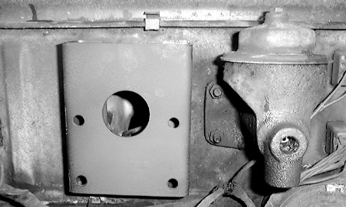
2. Bolt the rails to the firewall as shown below using the 5/16"NC X 1" bolts and split-loc washers provided. If you are doing this by yourself you can reach through the pushrod hole and start the 5/16" bolts. Make sure that the mounts are straight up and down. Don't tighten the bolts yet.
Remove the 1/4" pipe to 1/4" inverted flair fitting from the front opening on your clutch master cylinder and install it in the bottom opening after wrapping its threads with teflon tape. Wrap the 1/4" pipe plug (provided) with a little teflon tape and screw it into the end of the clutch master cylinder as shown. Make sure that the teflon doesn't extend over the end of the fittings or pieces of it may get loose in the hydraulic circuit causing problems. If your clutch MC only has one output opening use the old brake MC for the clutch as they usually have two openings (one for the brake light switch).
Because of the different firewall and distance between the firewall and the brake pedal a different type of booster adapter bracket is needed as shown below. Other than this the installation will be the same as for the '59-'60.
3. Unthread the push rod end from the Chevy booster and enlarge the hole in the end of the push rod from 1/2" to 9/16" so that it will fit your Dodge pedal bolt. Screw the pushrod back onto the booster.
6. Bolt the booster and master cylinder onto the adapter rails using the four 3/8"NC X 1" bolts provided. Check to make sure that the two master cylinder attach bolts on the booster are perfectly horizontal and the mount rails are vertical. If they are a little off, operation of the unit will not be effected, however it will be a visual irritation whenever you look at it!
Install the two master cylinder adapters in the outlet ports of the MC. The one that takes 1/4" brake line goes in the forward port and the one made for 3/16" line goes in the rear port. Run a 1/4" brake line from the forward port on the MC down to the top port on the brass brake line junction block on the left frame under the booster.
7. If you are installing a proportioning valve, fasten the adjustable proportioning valve onto its bracket using the two 1/4" x 1-1/2" bolts and nuts with the IN port facing forward and run a 3/16"X 8" length brake line from the rear MC resivour to the P-valve IN port. Your rear brake line will be brought up to the bottom of the Tee fitting which is installed in the other P-valve port marked OUT. Your hydraulic brake light switch is screwed into the rear opening on the Tee fitting.
Below is a photo of the brass brake line junction block located on top of the frame under the master cylinder. The 1/4" line from the forward port of the MC can be seen going into the top port. While the rear brake line has been unscrewed from the block and an extension line coupled to it, the extension goes up to the rear port of the MC. The remaining two lines go forward to the front brakes as in the original installation. A 3/16" flair plug is provided for plugging the rear line outlet in the block.
8. Drill a 3/8" hole 7/8" down from the original one and in the middle of the pedal bar. This is the new booster push rod attach point. This can be done without removing the pedal from the truck. It is a lot easier if you have someone checking the alignment of the drill bit for you while you do the drilling.
9. Screw the pedal shaft from step 4 on to the extension. On the installation I did the second 3/8" nut on the extension was not needed. If more pushrod length is needed on your installation you can use 3/8" SAE washers to increase the push rod length.
10. Attach the booster push rod to your pedal using the original 9/16" shoulder bolt and nut. You should have about 1/2" of free pedal movement before braking starts. Use the 3/8" hole you drilled instead of the original one.
11. Use the black foam tube provided to seal the dash opening. It is installed by wrapping it around the push rod under the dash. Remove the clear tape from the edges and they will glue themselves together. Now push it through the dash opening until it seals around the rubber boot on the booster shaft.
Proportioning valve adjustment:
These trucks are extremely light in the rear (especially the early short bed versions). Because of this you will want to start out with the P-valve adjusted all the way out CCW to full decrease for the first test run. Drive the truck on a dirt or gravel road with no other traffic at about 20 mph and lock up the brakes with someone standing a safe distance away watching your tires. At this point the fronts should lock up and skid while the rear wheels should keep turning.
If this is the case turn the P-valve in half way and try again, if your rear wheels still keep turning when the fronts lock up increase the pressure to the rear brakes 3 turns at a time until the rear wheels start to lock up at the same time as the fronts. If the rears lock up before the fronts after the half way adjustment then turn the valve CCW to decrease pressure to the rear 3 turns at a time until they lock at the same time. At this point you should turn the valve in the decrease direction (CCW) one or two turns.
The idea is to keep your rear tires from locking up and skidding on slippery surfaces under panic stop conditions. If there is too much pressure going to the rear brakes the truck will tend to "fishtail" causing loss of control. Once you determine the proper setting for your particular truck when it is empty mark the number of turns it takes to get to that position from full decrease position and write that number on the adjustment knob with a felt tip pen. Now when you have a load in the back of your truck and need additional stopping power you can screw the valve in a few turns to send more pressure to the rear brakes since you have several hundred pounds more weight holding the rear tires on the road and increasing their traction. Just remember to return it to the same setting as before when you have unloaded the truck.
All of the above is dependent on whether you have 4 wheel drums, or 4 wheel discs, or discs in front only. In the case of 4 wheel drum brakes or 4 wheel discs the P-valve will be almost to the full decrease position when properly adjusted. With front discs and rear drums more pressure will probably be needed to the rear brakes because of their lower braking power compared to the front discs. If you have problems with adjusting the proportioning or any other aspects of this installation you should contact us for help by email at rsuiter@helitool.com