
M37 MC Conversion
General information
We have tried several master cylinders on the M37 and the one used on the 1980 Chevy C30 1 ton trucks seems to be the best. With 4 wheel discs it is like having power brakes. This Master Cyl has a 1-5/16" bore which is close to the original MC bore size and provides plenty of volume even for 4 wheel discs. The most important reasons for doing this upgrade are:
1. To provide the added safety of a 2 circuit brake system, and
2. To enable you to install a proportioning valve in the rear line to keep your rear brakes from locking up during hard stops.
We have not tried to install a proportioning valve as yet, however the following are our thoughts on this subject.
This master cylinder does not have residual pressure check valves built into it. This makes it perfect for 4 wheel disc brakes which do not require residual pressure. If you have the original drum brakes on all 4 wheels, your best bet is probably to purchase a proportioning valve from the chevy dealer for the 1980 1 ton truck that goes with this master cylinder. This should have the residual pressure check valves in it (provided that you specify to the parts man that your truck has drums on the front instead of discs).
If you have disc brakes on the front only, you probably do not need a proportioning valve since the rear drums are so inefficient that the front discs are already providing 70% of the stopping power. The CarQuest part number for this master cylinder is 20-1584, the Bendix part number is 1584. You should be able to get it at other part stores by giving them the application (or the bendix number).
Installation
1. Remove the left running board and the original master cylinder.
2. You can either leave the left front mounting bracket on the truck or remove it, whichever seems easiest for you.
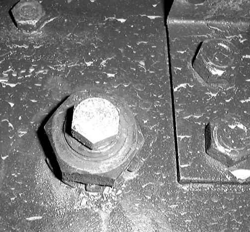
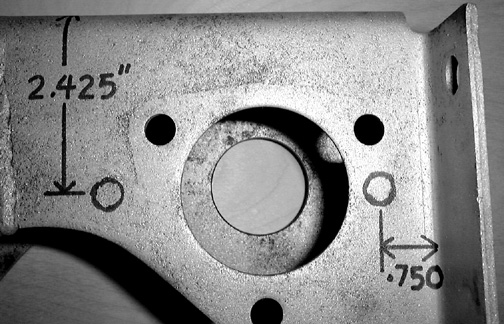
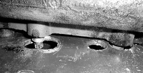
3. Below is a photo of the bracket with the location of the holes marked on it. The distance between the hole centers is 3.400". After laying the holes out set the master cylinder in place to check the accuracy. When you are sure that the hole locations are correct, drill them out using a 13/32"drill bit. For the 2.425" measurement lay a straight edge across the top ofthe bracket and measure from it.
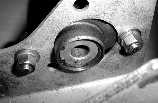
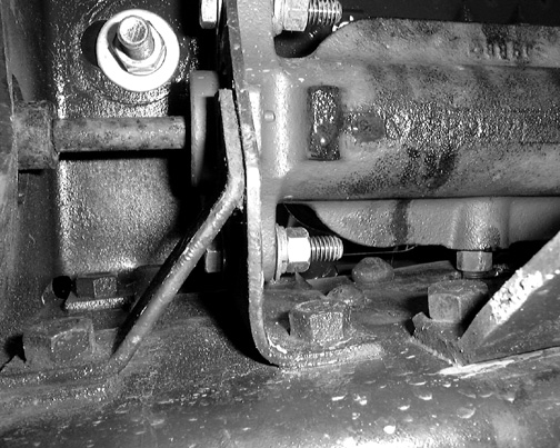
4. Below is a photo of the master cylinder mounted on the bracket using two 3/8" bolts. Notice that the MC is not centered in the opening but is moved outward away from the frame end as far as it will go, this is to provide clearance between the frame and the new master cylinder.
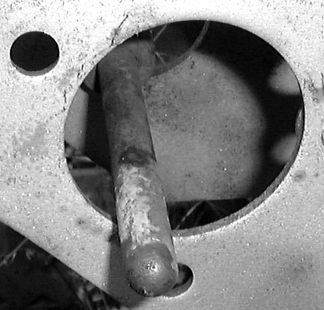
5. You can now remove the MC and hold the bracket at its original location and check to see that the push rod is lined up with the offset location of the MC. If it is not then bend it outward until it lines up. If your clevice is as worn as most are it will be so sloppy that this won't be necessary. The photo below shows the result that is needed.
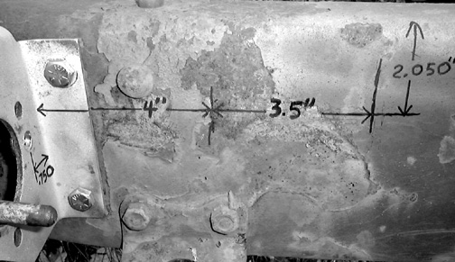
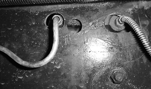
6. Next lay out the location of the two holes in the side of the frame that the brake lines will pass through. Use the photo below for the dimensions.
7. Now mount the bracket and MC in place on the frame and check the location of the holes you marked on the side of the frame for the brake lines to pass through.
8. If they line up with the outlets on the MC, remove the MC and drill them out using a 1" hole saw.
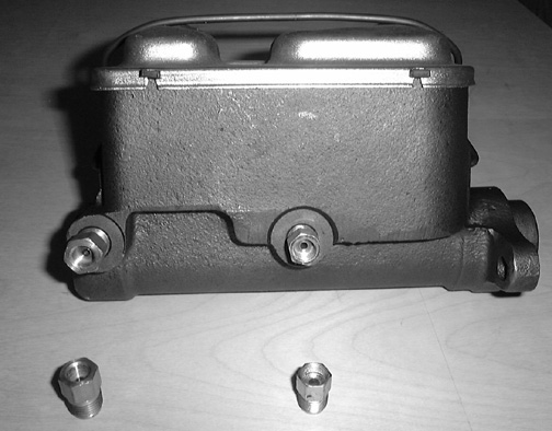
9. Next you will need to install 2 master cylinder adapters in the MC outlets so that you can connect the 1/4" lines that are used on the Dodge trucks. The photo below shows what these look like. They are made by Edelmann and the bendix brake co. If you can't find these locally we can send you a fitting kit that has them in it.
10. Reinstall the master cylinder on the bracket and plumb the front brake line into the front port on the new MC and the rear brake line into the rear port.
The photos below show how I did this and show how to hookup the brake light switch. The extra holes in the side of our frame are left over from other MCs we have tried.
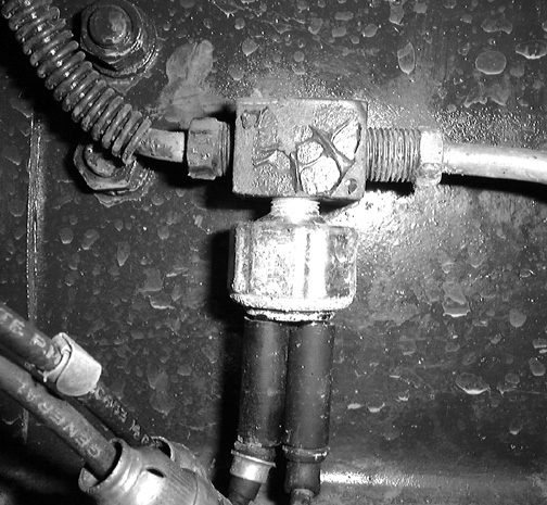
The photo below is of the inside of the frame
This is a view of the MC and the outside of the frame.
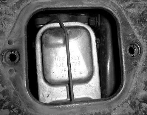
This photo is of the bottom of the MC.
With this installation you can service the MC through the original floor opening. Use a screwdriver to pry the bail off the cap.
Below is a photo of the outside of the frame showing the inverted flair plug that is used to cap the port for the original MCs outlet line.