M715 Disc Brake Conversion
W300 Disc Brake Conversion
Price: $595 plus shipping and 2 servicable hubs exchange
This disc brake conversion kit is for M715 Kaiser Jeeps with 16" or larger rims.
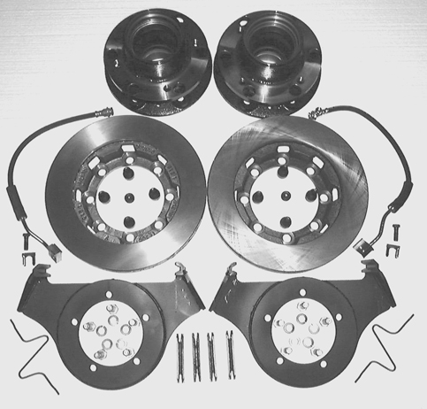
Conversion includes the following:
2 ea. 3/8" plate steel caliper brackets.
These bolt directly to the knuckle with no modification or welding required.
2 ea. Chevy Rotors.
Machined to fit rotor flange.
8 ea.5/8"NF X 1"bolts.
These attach the rotors to the rotor flanges.
10 ea. 1/2"NF X 1 1/2" grade 8 bolts and lock washers.
For attaching the caliper brackets to the knuckle.
4 ea. Caliper keepers.
For attaching calipers to caliper brackets.
2 ea. "Z" springs.
Keep caliper pads from rattling when brakes are not applied.
2 ea. Brake hoses and fittings.
For hooking the calipers up to the original hard lines.
You will need to purchase the following locally:
2 ea. 1994 Ford F350 1 ton calipers (right and left)
You will need to send us two front hubs so that we can install and machine rotor flanges. Remove the drums and send them with the races, axle studs and wheel studs in place.
Keep the drums in case you need to cut the ends out of them to use as spacer plates between the wheel flange and the wheel.
Disc brake installation instructions:
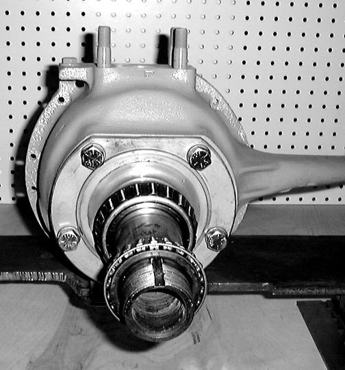
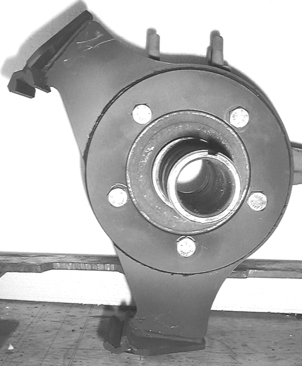
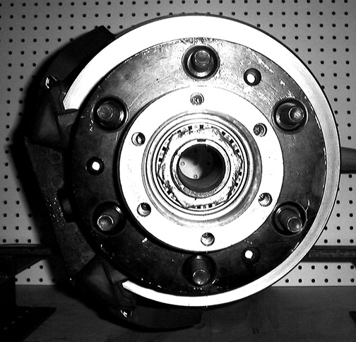
1. Remove the old hub, drum, shoes, wheel cylinder and backing plate from both knuckles. If your front axle hasn't been serviced lately this is a good time to do a complete tear down and replace the seals and bad bearings. The knuckle pictured below is for a Dodge W300.
2. Install the caliper brackets with the ears pointing aft and down (they can only be installed one way). Use the ten 1/2" NF X 1 1/2" bolts and spring lock washers to fasten them on the knuckles. Torque the bolts to 70 ft. lbs.

3. Remove the rotor bolts and rotors from the hubs.
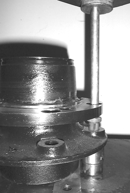
4. Drop the lug bolts through the large holes in the rotor flange that line up with their holes in the wheel flange. Rotate the lug bolts until you feel the serrations on the bolts engage the serrations in the holes. If the serrations are not aligned they will be damaged when the lug bolts are pressed in. Be sure to support the under side of the hub flange with a large socket when pressing the lugs in.
5. If your hubs are NOS they will not have serrations in the lug bolt holes and the lug bolts will make them as they are pressed in. You must press the bolts in perfectly vertical with a press piece whose ends are square to each other or the lug bolts will be cocked to one side and you will not be able to install the wheels.
6. Reinstall the rotors using the eight 5/8"nf socket head cap screws provided. Torque them to 80 ft. lbs.
7. Install a new inner hub seal and the snap ring that retains it. Pack the bearing cones with high temp. disc brake grease (also the entire interior of the hub). You should read the appropriate chapter of your trucks maintenance manual for proper installation of the hub and its nuts.
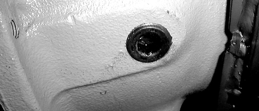
8.Prior to installing the caliper you will need to remove your knuckle lubrication plugs and replace them with the ones provided in the kit. They will need to be nearly flush with the top of the hole they fit into to clear the caliper. It would probably be a good idea to fill the knuckles with grease now, as you will have to remove one caliper to get to the plug in the future. You should also wipe the hub and rotor assembly down with lacquer thinner and paint the areas that require it.
9. Install the hub/rotor assembly on the spindle and adjust the spindle nuts according to the specifications in your TM.
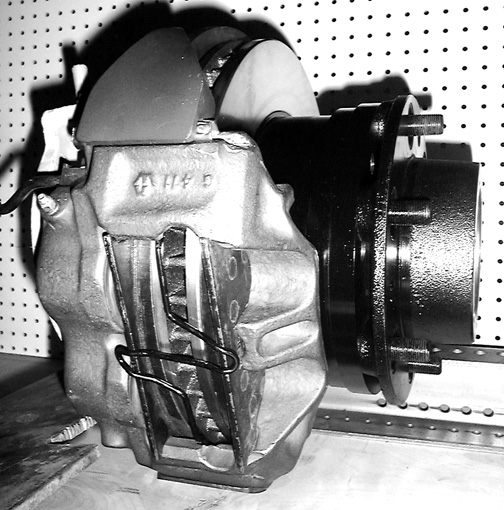
10. Next load the pads into the caliper (if a pad doesn't seem to fit try the other one, they are slightly different). Slide the caliper and pads in place (make sure that the bleeding nipple is pointing up and the cylinders are to the inside). Insert the keepers into the caliper rails with the raised tits on the ends pointed away from the caliper (they hold the keeper in place once it is installed. The center of the keeper is rubber so the two sides will compress as the keeper is tapped into place. When both keepers are in place install the "Z spring over the edges of the pads at the outside of the caliper (this keeps the pads from rattling).
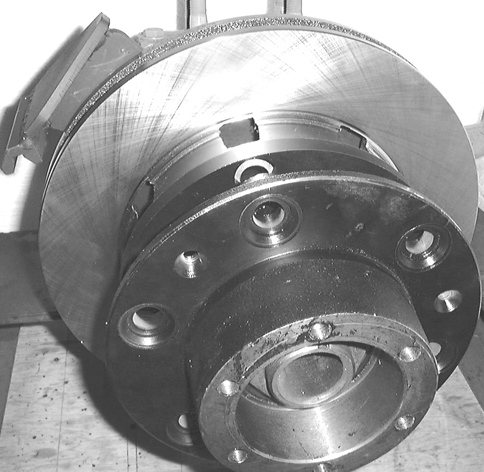
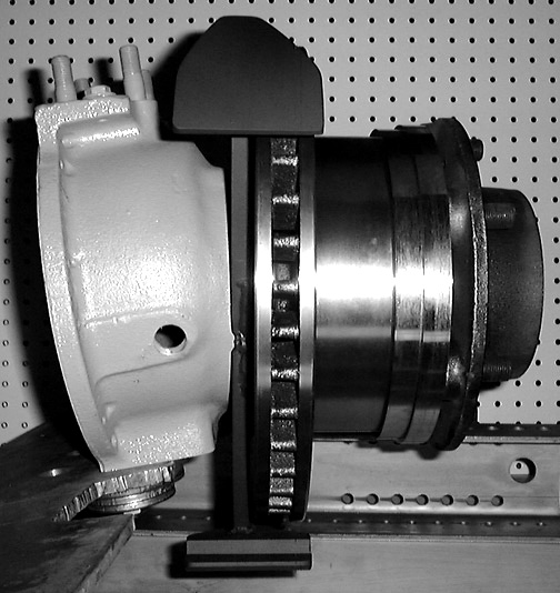
12. Below is a photo of the completed installation. All that is needed is to install the brake hose and bleed the system.
13. Now look at the inside heel of the caliper cylinders where they come closest to the knuckle. There should be at least .025" to .030" clearance between them (you can check this with a set of feeler gauges). If the clearance is less than this you will have to grind some metal off of that spot on the knuckle. Remember, the whole caliper moves inward approximately 1/4" as the pads wear.
14. If you want to check whether you have enough clearance simply remove the caliper pads, reinstall the caliper and slide it inward until it hits the knuckle then compare the gap that is left with the caliper pad thickness. Below is
a photo of the brake hose installed. There is a right and left hose.
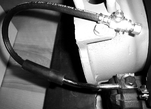
The adapter fitting screwed into the end is for 1/4" metal line if you have 3/16" metal lines remove this fitting and screw the metal line directly into the hose end.