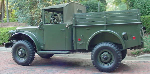
1951-1964 M37 Disc Brakes
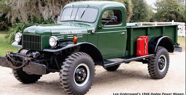
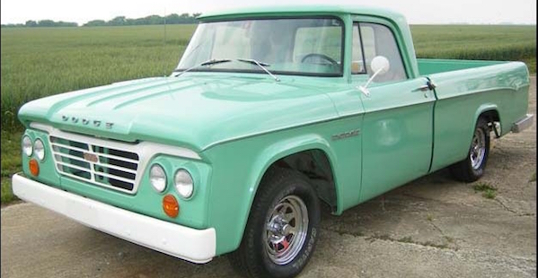
1946-1968 Civilian flat fender Power Wagon Disc Brakes
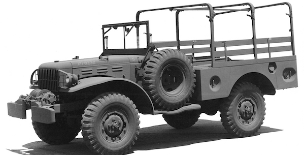
1942-1945 WC 3/4 Ton Weapons Carrier Disc Brakes
-
The same set fits both front and rear axles.
Price: $570 You will need to send your hubs to our machinist in Georgia to have them converted. Nothing changes as far as the total price of the brake set is concerned. You will pay us $450 for the brake set instead of the full price of $570 and send the additional $120 along with your hubs to the machinist for conversion. You will need to contact us by Email for hub shipping and payment instructions. (rsuiter@helitool.com)
Our disc brake conversion kit for Dodge Power wagons includes the following:
1. 2 ea. 3/8" thick wheel spacers. These take the place of the old drum and keep the lug nuts from bottoming out on their studs.
2. 2 ea. 3/8" plate steel caliper brackets. These bolt directly to the knuckle with no modification or welding required.
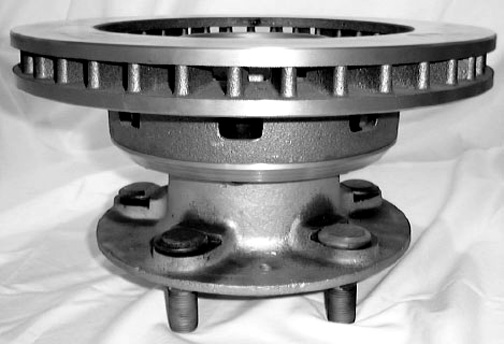
3. 2 ea. hubs with rotor mount flanges installed. Welded in place and machined true to spindle.
4. 16 ea. 5/8" NF X 1" grade 8 socket head bolts, lock nuts and washers for attaching the rotors to the hub rotor flanges.
6. 10 ea. 1/2" NC X 1 1/4" grade 8 bolts and lock washers. For attaching the caliper brackets to the knuckle.
You will need to purchase the following locally:
1. 2 ea. 78 - 87 GM 3/4 ton 4X4 rotors: (about $30 ea.)
2. 1 ea. 71 - 78 GM 3/4 ton 4X4 right caliper (about $60 with core charge)
3. 1 ea. 71 - 78 GM 3/4 ton 4X4 left caliper (about $60 with core charge)
4. 2 ea. Centric 150.62006 brake hoses or equivalent.
Rotor dimensional data:
Rotor OD 12.5"
Rotor depth 2 13/16"
Rotor thickness 1.285"
Rotor mount flange dia. 7 7/8"
8 bolt holes on 6.5" dia.
Caliper pin hole spacing 7.040"
Pad thickness .390"
Note: When sending hubs remove the large wheel studs and the 6 small axle studs keeping them for reinstallation in the hubs when we send them back to you.
Leave the old bearing races in the hubs.
installation instructions:
General information
I have tried to make the installation of this disc brake kit as easy as possible. No grinding, drilling or modification to the knuckle or calipers should be required. We install each set on a test fixture and check them both for proper fit and with a dial indicator for run out (the run out in thousands of an inch is written on the face of each rotor flange.)
Axial (lateral) run out should be .006" or less, radial run out can be as much as .010" without causing problems. Ours are usually .003" to .005" measured at the outside edge of the rotor ( 12.5" diameter)
Please refer to your particular trucks shop manual for proper procedures for removing and installing original parts such as hubs etc.
Wheel stud installation
We are no longer able to include new wheel and axle studs with our brake sets. Because of the poor condition of the ones that have been returned to us we have run out of new ones and can not find a reliable source for them. You will have to remove your old ones and replace any bent or damaged ones as best you can from other hubs or one of the parts suppliers.
If you use a hammer to remove them be sure to install a wheel nut even with the end of the bolt so that you don't damage the threads. When installing them in the new hubs we have sent, you will have to grind a small 45 degree angle on the flat side of the wheel stud head so that the stud can be rotated past the rotor flange.
Use an aluminum drift about 1" square by 12" long and a 3 lb. Hammer to drive the wheel studs into their holes. You must protect the rotor flange edge from the drift this is easily done by wrapping the area that comes into contact with the flange with a 1/8" layer of duct tape. You may also want to cut a donut out of 1/2" plywood to protect the face of the rotor flange incase you miss the drift when hammering the wheel stud in. The slightest defect in the surface of the rotor flange will cause the rotor to wobble.
The hole and stud diameters vary and if a stud is too tight or loose for one hole it might fit perfectly in another. If you have dial calipers you can measure to begin with and make this process easier. Dial calipers are available from places like Harbor Freight for as little as $10 and are very useful to have around the shop. If the fit is tight you should lubricate the stud before inserting it. If the fit is too loose, use some loc-tite of the permanent variety to secure it so it doesn't back out later.
Installation of front brakes
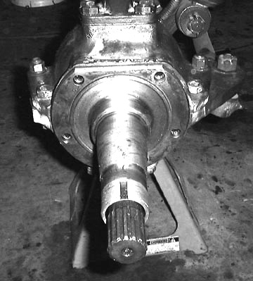
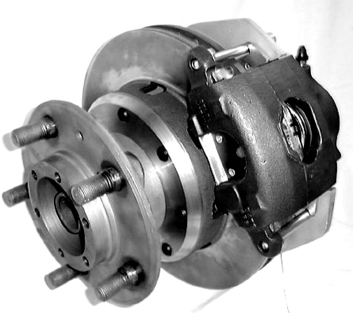
1. Remove the old hubs, drums, shoes, wheel cylinders and backing plates from the knuckles. They should now look like the photo below. Notice that both of the outside knuckle flange bolts have been removed and reinstalled with the nut side down. This provides extra clearance for the caliper. If your front axle hasn't been serviced lately this is a good time to do a complete tear down and replace the seals and bad bearings.
2. Install the caliper brackets with the ears pointing rearward and inboard ( they can only be installed one way). Use the ten 1/2" NC X 1-1/2" bolts and spring lock washers in the ziplock bag to install them on the knuckles. Torque the bolts to 70 ft. lbs. See photo 2 below.
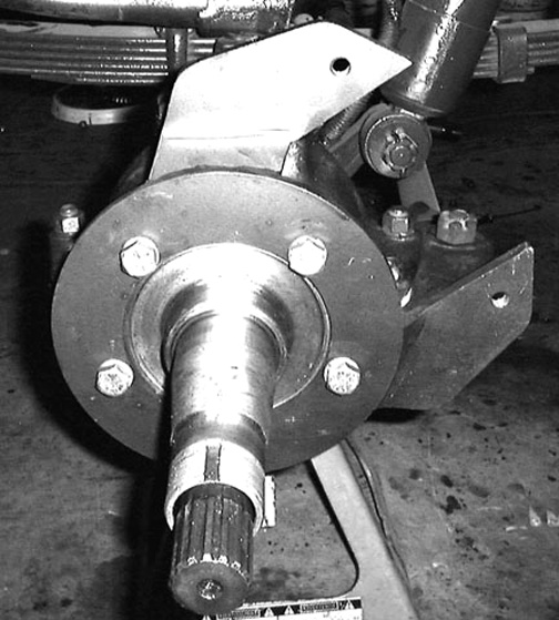
Photo 2
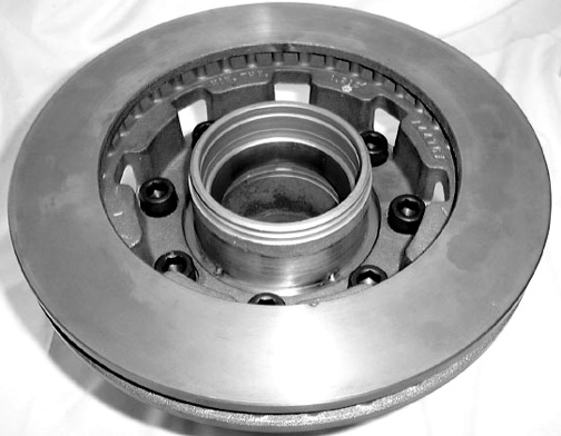
3. Place your rotors on the hubs as shown below.
4. Find the ziplock bag of eight 5/8" NF X 1" socket head bolts and use them to fasten the rotors to the flanges ( make certain that there are no burrs, dirt or paint between the rotors and the flanges). If the rotor that you are installing is a "tight fit" it may be necessary to temporarily install the bolts and use them to seat it (tighten the bolts evenly going from one to the other).
Use a 1/2" socket type Allen key on a 1/2" drive torque wrench to torque the bolts to 80 foot lbs. See photo below. (The rotor has 8 holes, install a bolt in every other hole).
5. Install new inner hub seals and the snap rings that retain them. Pack the bearing cones with high temp. disc brake grease (also the entire interior of the hub). You should read the appropriate chapter of your trucks maintenance manual for proper installation of the hub and its nuts.
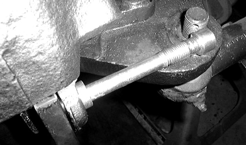
6. Before installing the calipers modify the lower caliper pins by grinding a flat on one side as shown below. This is necessary to clear the tie-rod bolt.
7. Next install the calipers with their pads in place (make sure that the bleeding nipples are pointing up and the cylinder is to the inside). It will be necessary to remove the tie-rod nuts to provide clearance for the lower caliper pin as shown below.
8. Insert the caliper pins from the back side through the caliper, then through the 7/16" NF threaded holes in the caliper bracket ears, under the inside pad hooks, through the holes in the outside pads, and finally through the outer caliper holes. After you tighten down the caliper pins against the caliper pin bushings it should look like this. Be careful not to cross thread the caliper pin. Use your fingers to start it as you wiggle the opposite end to get the alignment right.
Note: if the caliper seems to be too far out for it to fit over the caliper bracket this may be caused by an outside pad lining that is a little too thick. If it is only a few thousandths too thick use a disc or belt sander to remove the excess. Before doing this make certain that the problem is not caused by an improperly seated outside pad.
9. Below is a close up of the caliper pin installation, notice how the inside pad has a hook that rides on top of the pin. Failure to install both of these hooks as shown may allow the pad to drop down out of position resulting in partial or complete brake failure.

10. Now look at the inside heel of the caliper cylinder where it comes closest to the knuckle. There should be at least .025" to .030" clearance between them (you can check this with a set of feeler gauges). If the clearance is less than this you will have to grind some metal off of that spot on the knuckle. Remember, the whole caliper moves inward approximately 3/16"as the pads wear. If you want to check whether you have enough clearance simply remove the caliper pads, reinstall the caliper and slide it inward until it hits the knuckle then compare the gap that is left with the caliper pad thickness.
11. Next, with the caliper and pads installed look at the top of the pads. You will notice that they stick up above the rotor approximately 1/16". This is not a problem, however there is a simple modification to the pads that can be made that will bring the tops down even with the top of the rotor. If you are a neophyte don't bother. If on the other hand you are an experienced mechanic turn to the last page in this booklet for instructions.
Don't forget to reinstall and safety the tie-rod nuts.
At this point you need to hook up your new disc brakes to the brake lines. This can be accomplished in the following way.
Hooking up to your hard lines
The following brake parts can be purchased from a Carquest or NAPA parts store. I'm sure that they are available elsewhere as well.
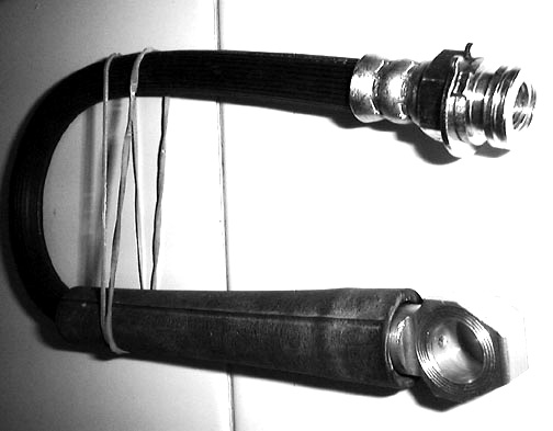
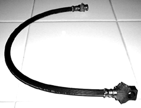
1. Below is a photo of a GMC brake line that is compatible with this caliper and is the same length as the original Dodge hose. It was purchased from a CarQuest parts store and it's part number is BWC SBH1022 (NAPA# 36713 '74-'76 Monte Carlo). It is different in two ways. It's inlet has 3/8"NF threads for 3/16" metal brake lines instead of 7/16"NF for 1/4"( the metal line that is used on the Dodges). Also the end that attaches to the "L" shaped axle bracket uses a horse shoe clip instead of a nut to secure it.
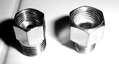
3. There are two fittings that are made by the Edelmann company. One changes a 3/8"NF flare to a 7/16"NF flare it's part number is 258430. The other one is a part number 258340. It reduces a 7/16" flare to a 3/8" flare. You can use these to go from one brake line size to the other (keep this to a minimum as each one you add is another potential leak looking for a time to happen) The photo below shows what these two fittings look like. They are called "master cylinder adapter fittings" and cost about $2.00 each.
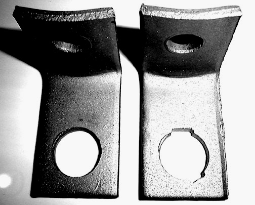
4. There are two locator tabs on the end of this hose that fit into corresponding slots in the axle bracket. These are easily reproduced in your "L" shaped axle brackets by removing them from the axle and holding the hose end up to the 5/8" dia. hole and marking their location with a scribe then using a 6" long by 3/16" triangle file to file them into the edges of the hole. The end result is shown below. The original bracket is on the left and the modified one is on the right.
5. Below is a photo of the hose and bracket assembly with it's horse shoe clip (CarQuest part number W72-2) installed and the Edelmann fitting screwed into the inlet. All that is needed is to push the horse shoe clip the rest of the way down into the groove.
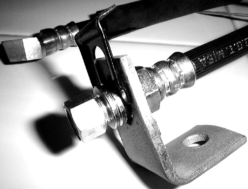
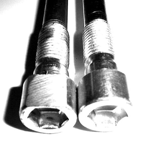
6. If you are using the modern GMC flex hose just described do not use the original Dodge banjo bolt and copper washers, they are not compatible with the the modern hoses. You will need to purchase new GMC bolts (the correct copper washers come with the calipers). Be aware that there are two different lengths, a long and a short. The one you want is the short one (it measures 9/10" from its end to the underside of the head). If you get the long one by mistake you will know it because the threaded end will bottom out and the line end will still be loose. This bolt is made by Bendix Brake Co. its part number is 96100.
7. If you are replacing your frame to axle hoses there is a modern equivalent for them. It's part number is BRK SP4520 and it is pictured below. It is a bit pricey at $38.32 ea. but is easily obtained from CarQuest.
8. Metal brake lines are carried by most auto parts stores. They come in various lengths (8" to 60") and diameters (3/16" to 3/8") they are usually made by Edelmann. If you are still using the original lines that the truck came with change them, they are probably badly rusted inside if not outside. On the following pages are some pictures of the rear axle of an M37 showing the installation of the metal and rubber flex lines.
Hard line installation
The photos that follow are of an M37, the same information applies to power wagons as well.
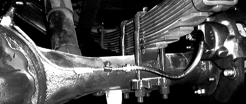
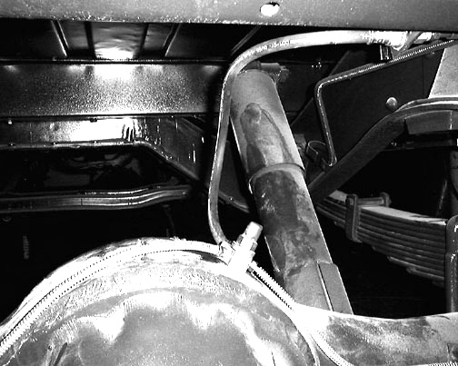
The photo below shows the right rear axle. The metal line is a 3/16" X 12" "armor wrapped brake line part number BL3312. It is screwed into the SBH1022 flex line at the caliper cylinder and into the outlet end of the SP4520 frame to axle hose (the inlet end is inserted into the "L" bracket on the frame and a horse shoe clip installed to hold it. The end of the metal line that attaches to the caliper hose has a 1" piece of 3/8" I.D. fuel hose split and wrapped around it before inserting the line into the original metal clip. Use a pair of pliers to close the clip around the line.
>
Below is the left side of the same axle. A BL3330 (30" long) 3/16" armor wrapped brake line is used on this side. Installation is the same as the other side except that a longer metal line is used. It will be necessary to bend the ends of the metal lines aft a little so that the hoses clear the spring U-bolts.
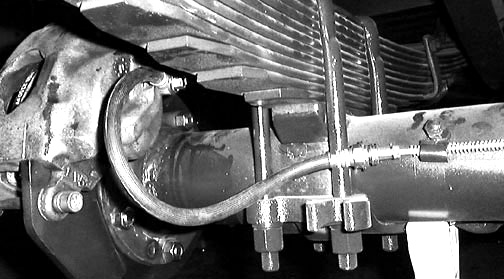
Below is a photo of the center of the same axle. The two metal lines are screwed into the SP4520 frame to axle hose outlets and the upper end is attached to the "L" bracket on the frame. You can either continue on to the master cylinder with 3/16" metal line or use one of the "master cylinder adapters" to change to 1/4" metal line for the run up to the master cylinder.
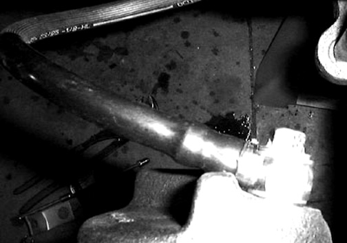
Below is a photo of the rear caliper flex hose taken looking down on the caliper cylinder.
Rear disc brake installation
The installation of the rear disc brakes should be easier than the front since there is no knuckle to deal with. Unfortunately there are 10 half inch steel rivets that have to be dealt with! This is best done with a large variable speed 1/2" drill (and a couple of friends).
First center punch the heads of all the rivets. Then drill a 1/4" dia. hole 3/4" deep, being careful to keep it centered. Follow up with a 1/2" bit, then shear the heads off with a 5 lb. hammer and cold chisel. Next use a 7/16" drift to knock them out of the holes. Be very careful when using one of these large drills they can very easily break your wrist if the drill bit catches!
Once you get the rivets out the installation is the same as the front.
Wheel spacer installation
When installing the wheel spacers make sure that the wide chamfer on the large inside hole is facing the hub not the wheel.
Checking for valve stem clearance
When you have mounted the wheels rotate them so that the inner tube valve stem is next to the caliper. If it looks like there is any chance that the valve stem may hit the caliper you will need to move the valve stem towards the outside of the wheel in it's slot. This will need to be done with the tire deflated , I use a vacuum pump to completely deflate the inner tube, then slit the rubber tube flap in the direction the stem should go, then use a screw driver to move the stem over. I suggest that you have a tire shop do this, it's safer.
Replacing wheel studs
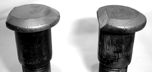
If you ever break a lug bolt you will have to modify the new one by grinding the flat side of the head to approximately a 40 deg. angle as shown below. This is done so that the head of the bolt can clear the rotor flange during installation.
Brake pad modification
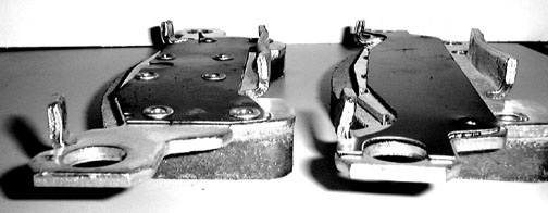
Below is a photo of a modified pad (left) and an unmodified one (right). All that has been done is to bend the metal locator tabs on the left side vertical and the ones on the right side a corresponding amount towards the other ones. This will shift the pad downward in the caliper 1/16" Make sure the pad fits with the same tightness as before you bent the tabs when you reinstall it in the caliper.
Below is the cylinder side pad. All you have to do here is remove the center spring clip and reinstall it in the opposite direction so that it pushes the pad down against the caliper pins instead of up. The unmodified pad is on the bottom and the modified one at the top.