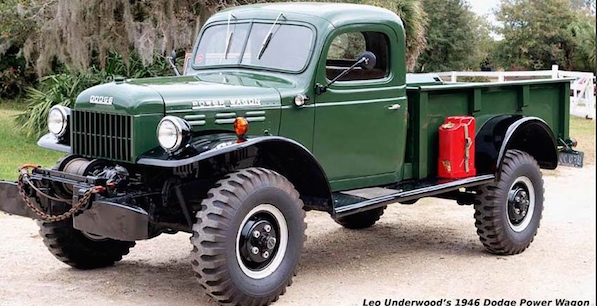
1945-1967 Civilian Power Wagon Hanging Pedals
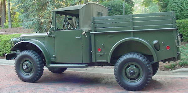
1952-1964 M37 Hanging Pedals
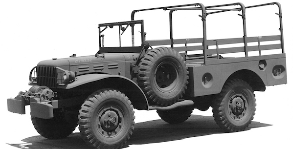
1942-1945 WC 3/4 Ton Weapons Carrier Hanging Pedals
This pedal assembly mounts to the inside of the firewall. To install a hole pattern is drilled consisting of two 1" holes for the master cylinder push rods, three 5/16" holes to attach the clutch master cylinder and six 3/8" holes for attaching the brake booster and master cylinder.
We have tried to maintain the same size and shape pedals as the original and kept them in the same location except that they are two inches closer to the firewall which provides much needed leg room. This unit is primarily intended for owners who have installed a V8 and power steering although it will work on a stock truck as well.
$310.00 plus shipping.
Includes clutch and brake pedals mounted on 1/8"plate, installation hardware and master cylinder adapters.
You will need to purchase the following:
1. 1976 Chevy C30 one ton dual diaphragm booster. $120
1. 1976 Chevy C30 one ton master cylinder. $ 43
1. 1961-1968 Dodge truck clutch master cylinder. $ 55
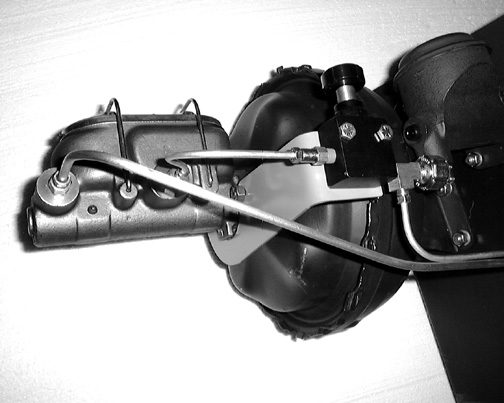
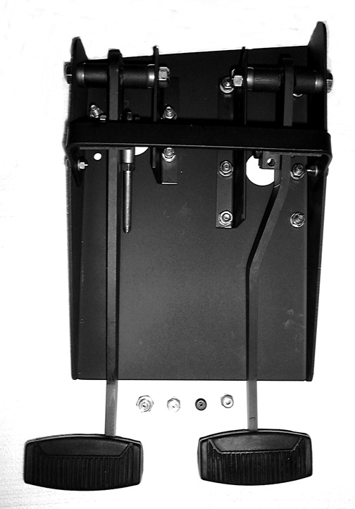
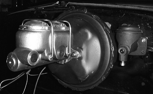
Below is a photo of the pedal assembly with the master cylinders attached. The only thing that is missing is the firewall which is sandwiched between the pedal plate and the master cylinders.

Below is a photo of the master cylinders mounted to the firewall.
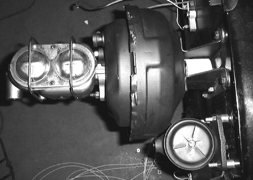
Below is a top view of the installation.
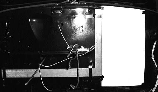
View looking up under the dash board. The reason for using such a large mount plate is to reinforce the dash to keep it from flexing when the pedals are pressed.
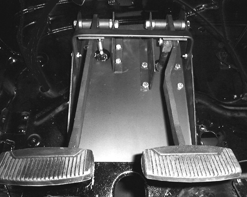
View from drivers seat showing position of pedals, steering column and accelerator pedal.

Installation instructions
Drilling the hole pattern:
The only difficult part of the installation is making sure that the hole pattern is drilled in the correct location. Once that is done it only takes a couple of hours to bolt everything together.
1. Begin by removing everything that is attached to the firewall both inside and out in the area that the mount plate will occupy. It should not be necessary to remove the steering column however the brace that goes from the top of the firewall to the steering column attach point on the dash must be removed and can't be used with the pedal installation.
2. Check the inside surface of the firewall for hole edges that rise above the surface and would keep the mount plate from laying perfectly flat against the inside of the firewall. Grind any that you find flush with the firewall surface.
3. Use a 24"X 16" square to align the inside edge of the template provided so that it is perfectly parallel to the vertical centerline of the firewall. The easiest way to do this is to align the long edge of the square with the lower edge of the firewall where it is spotwelded to the bellhousing cover. The other arm of the square should now be vertical and can be used to align the edge of the template. The curved top of the template fits up under the cowling lip as far as it will go.
4. While someone holds the template in place on the outside you should check to see if the steering column opening in the bottom of the template lines up with the actual opening in the firewall. Move the template side ways keeping it vertical until it does line up. Now check the oval wire opening in the firewall that is about half way up the right side of the template (as viewed from the inside). The edge of the template should cover 1/4" of the side of this hole.
5. When you are sure that the template is properly positioned use a center punch to transfer the location of the holes as marked on it to the firewall. The lower outside bolt for the clutch master cylinder is not used so this hole doesn't need to be drilled
6. remove the template and drill out the two uppermost holes on each side of the template. One will be 3/8" the other is 5/16". They will be used to test mount the pedals to check for proper position.
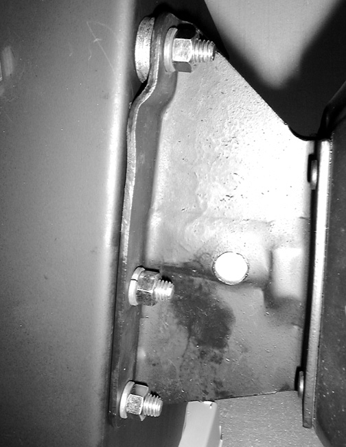
7. Mount the pedals under the dash using the two holes and bolts pictured below.

8. Once the pedals are mounted using only these two bolts you must check for proper poisoning and to make certain that they are perfectly vertical. Once this is determined leave the pedal mount plate in position after removing the pedals themselves. You can now go to the engine side of the firewall and use a 1/8" drill to drill the center punches you made, checking each one from the inside to make sure it is acutely in the center of its corresponding hole in the mount plate. If they are off a little you now have an opportunely to correct the location when you enlarge the holes to their final size. Note that the 1" hole for the booster pushrod will not line up with the 1-1/2" hole in the mount plate, it will be about 1/4" off center towards the top. Make sure that the two 1" holes are centered in the 1" wide vertical firewall ribs that are about 6" apart.
Alternate method of drilling:
When The pedal plate is in its correct position supported by the two bolts, as described above. Tighten the two bolts and clamp the lower edge of the plate to the firewall using a C-clamp at the firewall cutout where the steering column goes through. Then drill the remainder of the holes from the inside under the dash using the plate itself for a template. This is the most accurate method but is somewhat difficult because of the tight courters and wiring. Be sure to wear lots of eye protection as chips will be dropping down in your face while drilling.
Bolting up the components: (for clarity the assembly is done without the firewall between the mount plate and the components).
1. When all of the holes are drilled in the correct locations you can rehang the mount plate as before using the two upper bolts and their nuts.
2. Now install the booster using the six 3/8" bolts provided as shown below. The two longer bolts go in the top along with 2 spacer washers on each side (it may be easier to install the top two bolts from the engine side of the firewall).
3. Next install the clutch master cylinder using the three 5/16" x 1-3/4" bolts and spacers. The fourth bolt is left out because of interference with the radiator rod bracket on the firewall. Screw the brass 1/4" pipe to 1/4" brake line adapter into the lower port on the master cylinder and the 1/4" pipe plug into the end port to close it. Use a couple of wraps of teflon tape on each, making certain that none of the tape is within two threads of the end, otherwise pieces of it might get loose in the fluid and cause blockage.
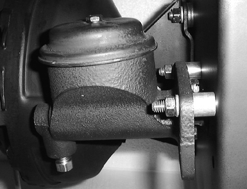
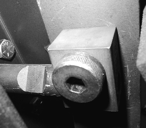
4. Next move inside and screw the booster pushrod block onto the pushrod. Note that one side of the 3/8" threaded hole in the block has 1/4" of threads removed, this end threads onto the pushrod first. Now hold the brake pedal in place and install and tighten the 1/2" shoulder bolt after applying a little grease to it. Install the 3/8" lock nut and tighten it.
5. Grease and install the brake pedal pivot bolt and thrust bearings and tighten its lock nut until there is no side play in the pedal (don't over tighten). A couple of drops of gear lube should be put in the thrust bearings prior to installation.
6. Hold the clutch pedal in place and insert the clutch pushrod into the clutch master cylinder piston and bolt its rod end to the arm using the 3/8" bolt, lock washer and nut provided.
7. Grease and install the clutch arm pivot bolt and thrust bearings the same as for the brake in step 6.
8. Install the two master cylinder adapters into the MC ports as shown below. They convert the ports to take your 1/4" brake lines.
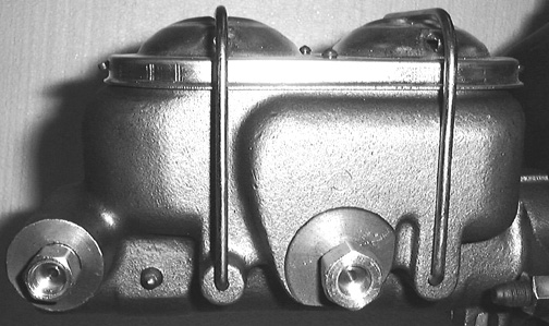
9. If you are not installing an adjustable proportioning valve hook your rear brake line to the rear port and the front line to the front port. Technicaly, the front brakes normally go to the larger resivour, however in actual practice either one will work as well as the other.
Proportioning valve installation:
If you are installing our adjustable proportioning valve and bracket the suggested line routing is shown below. The front outlet goes to the front brakes and the rear one goes to the in port on the proportioning valve. The output from the P-valve goes through a tee fitting which accepts the rear brake line and the brake light switch. The bracket itself is attached to the two master cylinder studs using two extra nuts and there is no need to undo the master cylinder to install it.